Have you ever wanted to control how bright a light is or how fast a motor runs? With Arduino, you can do just that using a command called Analog Write. It lets you adjust the power level going to devices, so instead of just turning things on or off, you can choose exactly how much power to send. This means you can make an LED softly glow or a motor spin at just the right speed.
Analog Write allows you to control the level of power sent to a device. Unlike digital Write, which only turns things fully on or off, Analog Write lets you set a specific power level. This is really important when you need to adjust brightness, speed, or any other variable in your project.
Analog Write
Choose a Pin: You can use Analog Write on certain pins that have a ~ symbol next to their number (For Arduino UNO pins 3,5,6,9 to 11).
Set the Power Level: Use analogWrite(Pin, Value); to control how much power is sent. The value can be any number from 0 (completely off) to 255 (fully on).
Analog Write Example: Dimming an LED
Hardware Requirements
1x Arduino UNO
1x 220R Resistor
1x Led
1x breadboard
Some jumper wire
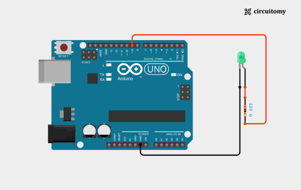
Circuit Diagram

Fig: Interfacing led with Arduino
LED Connection:
| LED Pin | Arduino Pin |
| LED’s Positive (Anode) Pin | D9 (Digital Pin 9) |
| LED’s Negative (Cathode) Pin | GND |
Code
// Set pin number
int ledPin = 9;
int brightness = 0;

void setup() {
  // Initialize the LED pin as an output
  pinMode(ledPin, OUTPUT);
}

void loop() {
  // Increase brightness
  for (brightness = 0; brightness <= 255; brightness++) {
    analogWrite(ledPin, brightness);
    delay(10);
  }

  // Decrease brightness
  for (brightness = 255; brightness >= 0; brightness--) {
    analogWrite(ledPin, brightness);
    delay(10);
  }
}
1. Set the PIN Number
int ledPin = 9;
int brightness = 0;
ledPin = 9; This assigns pin 9 on the Arduino as the pin where the LED is connected.
brightness = 0; This sets up a variable named brightness, which will be used to control the brightness level of the LED. It starts at 0, meaning the LED is initially off.
2. Setup Function
void setup() {
  // Initialize the pin as an output
  pinMode(ledPin, OUTPUT);
}
pinMode(ledPin, OUTPUT); This tells the Arduino that pin 9 will be used to send signals out (output) to the LED.
3. Loop Function
void loop() {
  // Increase brightness
  for (brightness = 0; brightness <= 255; brightness++) {
    analogWrite(ledPin, brightness);
    delay(10);
  }

  // Decrease brightness
  for (brightness = 255; brightness >= 0; brightness--) {
    analogWrite(ledPin, brightness);
    delay(10);
  }
}
I . Increasing Brightness
  for (brightness = 0; brightness <= 255; brightness++) {
    analogWrite(ledPin, brightness);
    delay(10);
  }
a) for (brightness = 0; brightness <= 255; brightness++): This loop gradually increases the brightness value from 0 to 255.
b) analogWrite(ledPin, brightness); This line sends the current brightness value to the LED on pin 9, adjusting its brightness.
1. A value of 0 means the LED is completely off.
2. A value of 255 means the LED is at its brightest.
c) delay(10); This pauses the loop for 10 milliseconds, creating a smooth transition as the brightness increases.
II . Decreasing Brightness
  for (brightness = 255; brightness >= 0; brightness--) {
    analogWrite(ledPin, brightness);
    delay(10);
  }
a) for (brightness = 255; brightness => 0; brightness–):This loop gradually decreases the brightness value from 255 to 0.
b) analogWrite(ledPin, brightness);This line adjusts the brightness of the LED on pin 9, making it dimmer
c) delay(10);This again pauses the loop for 10 milliseconds, allowing the brightness to decrease smoothly.
This code makes the LED connected to pin 9 gradually increase in brightness from off (0) to full brightness (255) and then gradually decrease back to off. It creates a smooth “breathing” or “fading” effect, with the LED getting brighter and dimmer in a continuous loop.
Applications
LED Fading in Light Displays:
You can use this pattern in decorative lighting systems or displays where smooth transitions of light brightness are needed, such as in mood lighting or art installations.
Dimming Control for Motors or Fans:
This approach is applicable to motor control, where a similar fading pattern can be used to control the speed of DC motors or fans by adjusting their voltage via PWM.
Analog Device Control:
Any analog device that supports PWM control (e.g., servo motors, audio volume, etc.) can benefit from this type of control loop.
User Interfaces:
Gradual brightness changes can be used in user interfaces to make transitions smoother, such as fading in or out indicators, displays, or buttons.
Power Management:
In power-sensitive applications, you could use a similar approach to dynamically adjust power usage by controlling device brightness or motor speeds depending on current load or requirements.
You can further modify the code to introduce more complex behaviors like varying the speed of fading or controlling multiple LEDs or devices simultaneously.
