We’re going to explore the cool realm of LDR sensors and Arduino microcontrollers! You’ll learn how light-dependent resistors (LDRs) work with Arduino to create fun and useful projects. Let’s light up our knowledge and dive into awesome LDR and Arduino projects together!
Introduction to LDR
An LDR (Light Dependent Resistor) is a sensor that detects light levels. It’s commonly used in devices like streetlights, automatic lamps, and light meters to sense the brightness around them.

Working Principle
The LDR’s resistance changes based on how much light hits it. In bright light, its resistance drops, allowing more electrical current to pass through. In darkness, its resistance increases, restricting the current. By connecting an LDR to a microcontroller like an Arduino, you can measure this change in resistance and use it to control things like lights or alarms based on the surrounding light levels.
Hardware Requirements
1x Arduino UNO
1x 10k Resistor
1x LDR
1x breadboard
Some jumper wire
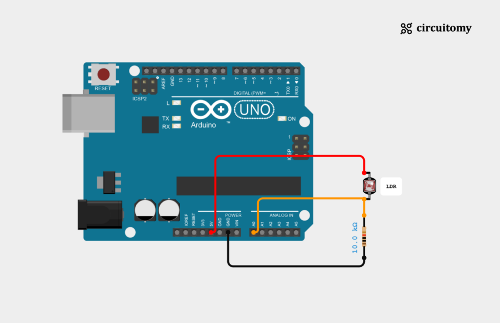
Circuit Diagram

Fig: Interfacing LDR Sensor with Arduino
LDR Sensor Configuration
| LDR Pin | Arduino Pin |
| LDR one leg pin | 5V |
| LDR other leg | A0 (Analog Pin 0) |
| Place a 10kΩ resistor between Analog Pin A0 and GND. |
To set up the circuit, connect one leg of the LDR (Light Dependent Resistor) to the 5V pin on the Arduino board and connect its other leg to analog pin A0. It’s essential to add a 10k resistor in series with the LDR to form a voltage divider circuit accurately.
Code
const int ldrPin = A0;  // LDR connected to analog pin A0
int adcValue = 0;       // Variable to store the ADC value
float voltage = 0.0;    // Variable to store the converted voltage
const float referenceVoltage = 5.0; // Reference voltage (5V for most Arduino boards)

void setup() {

  Serial.begin(9600);   // Initialize serial communication

}

void loop() {

  adcValue = analogRead(ldrPin);  // Read the ADC value from the LDR
  // Convert ADC to voltage
  voltage = (adcValue / 1023) * referenceVoltage;

  Serial.print("ADC Value: ");
  Serial.print(adcValue);
  Serial.print(" - Voltage: ");
  Serial.println(voltage);  // Print the voltage to the serial monitor
  delay(500);  // Delay for readability
}
1. Set the PIN Number
const int ldrPin = A0;  // LDR connected to analog pin A0
int adcValue = 0;       // Variable to store the ADC value
float voltage = 0.0;    // Variable to store the converted voltage
const float referenceVoltage = 5.0;
I) ldrPin : Defines the analog pin (A0) where the LDR is connected.
II) adcValue : Stores the raw analog reading from the LDR. It will be a number between 0 and 1023, as Arduino’s analog-to-digital converter (ADC) is 10-bit.
III) Voltage : Used to store the calculated voltage from the raw analog reading.
IV) referenceVoltage : The reference voltage for the Arduino (usually 5V), used for the voltage conversion calculation.
2. Setup Function
void setup() {
  Serial.begin(9600);   // Initialize serial communication
}
I) Serial.begin(9600); Initializes communication between the Arduino and the computer at a baud rate of 9600. This allows the Arduino to send data (like sensor readings) to the Serial Monitor on your computer.
3. Loop Function
void loop() {

  adcValue = analogRead(ldrPin);  // Read the ADC value from the LDR
  // Convert ADC to voltage
  voltage = (adcValue / 1023) * referenceVoltage;

  Serial.print("ADC Value: ");
  Serial.print(adcValue);
  Serial.print(" - Voltage: ");
  Serial.println(voltage);  // Print the voltage to the serial monitor
  delay(500);  // Delay for readability
}
I) adcValue = analogRead(ldrPin); : Reads the analog value from the LDR connected to pin A0. The value will range from 0 (no light) to 1023 (maximum light).
II) voltage = (adcValue /1023) * referenceVoltage; : Converts the raw adcValue into a voltage. The formula divides the raw value by 1023 (the maximum ADC value) to get a fraction, then multiplies it by the reference voltage (5V). This gives the actual voltage measured at the LDR.
III) Serial.print(“ADC Value: “); : Sends the text “ADC Value: ” to the Serial Monitor.
IV) Serial.print(adcValue); : Sends the raw ADC value (the light reading) to the Serial Monitor.
V) Serial.print(” – Voltage: “); : Sends the text ” – Voltage: ” to the Serial Monitor.
VI) Serial.println(voltage); : Sends the calculated voltage value and moves to the next line in the Serial Monitor.
VII) delay(500); : Pauses the loop for 500 milliseconds (0.5 seconds) to make the readings easier to view and avoid flooding the Serial Monitor with data.
Summary:
1. The Arduino reads the LDR’s analog value.
2. It converts this value into voltage.
3. It sends both the raw value and the voltage to the Serial
4. The loop repeats every 500 milliseconds.
Serial Terminal:


Light Condition (Bright Environment):
1. LDR Resistance: In bright light, the LDR’s resistance decreases.
2. Voltage: When the LDR’s resistance is low, more voltage is available at the point where it’s connected to the Arduino’s analog input pin. This results in a higher voltage.
3. ADC Value: Since the Arduino’s analog input reads voltage and converts it to an ADC value between 0 and 1023, a higher voltage means a higher ADC value. So, in bright light, the ADC value will be closer to 1023.
Dark Condition (Low Light or No Light):
1. LDR Resistance: In the darkness, the LDR’s resistance increases.
2. Voltage : When the LDR’s resistance is high, less voltage is available at the point where it’s connected to the Arduino’s analog input pin. This results in a lower voltage.
3. ADC Value : A lower voltage leads to a lower ADC value, closer to 0. So, in dark conditions, the ADC value will be much lower.
The Arduino converts this voltage reading into an ADC value, which represents the light intensity detected by the LDR. By using these values, you can program your Arduino to perform actions based on the amount of light or darkness.
