Flame sensors are simple and powerful tools that help detect the presence of fire, making them valuable for safety and monitoring systems. In this tutorial, you’ll learn how to connect a flame sensor to an Arduino, understand its working principle, and use both its digital and analog outputs to create a fire detection system.
A flame sensor is a small electronic device used to detect the presence of flames or fire. It works by sensing the infrared (IR) light emitted by flames. These sensors are commonly used in fire alarms, safety systems, and robotics.
Key Features of a Flame Sensor:
I) Digital Output (DO): Detects flames and provides a simple HIGH or LOW signal.
II) Analog Output (AO): Measures the intensity of the flame, providing a value between 0 and 1023.
III) IR Sensor: The main component that detects infrared radiation from a flame.
Flame Sensor Working Principle
A flame sensor works by detecting the infrared (IR) radiation emitted by flames. The main component of the flame sensor is an infrared receiver, which can sense IR light within a specific wavelength range, typically around 760 nm to 1100 nm. When a flame is present, it emits IR light, which is captured by the sensor’s IR receiver. This light is converted into an electrical signal, indicating the presence of a flame.
The sensor outputs this signal in two forms: a digital output (DO) and an analog output (AO).
The digital output gives a simple on/off signal, changing from HIGH to LOW when a flame is detected. This is ideal for basic applications where we only need to know if a flame is present.
On the other hand, the analog output measures the intensity of the flame, providing a continuous range of values based on how strong or close the flame is to the sensor. By adjusting the potentiometer on the sensor, you can fine-tune its sensitivity to flames, making it a versatile tool for fire detection and safety applications.
This dual-output design allows the flame sensor to be used for both simple flame detection and intensity measurement, making it suitable for a wide range of projects from basic fire alarms to more advanced monitoring systems.
Sensor Specifications and pinout:
Flame Sensor Specifications
I) Voltage Supply: 3.3V to 5V
II) Current Consumption: Around 20mA
III) Detection Angle: Approximately 60 degrees
IV) Detection Wavelength: 760 nm to 1100 nm (optimal for flame detection)
V) Analog Output Range: 0 to 1023 (varies based on flame intensity)
VI) Digital Output: HIGH (no flame), LOW (flame detected)
VII) Detection Range: Up to 1 meter, depending on flame intensity and sensitivity setting
Pinout:
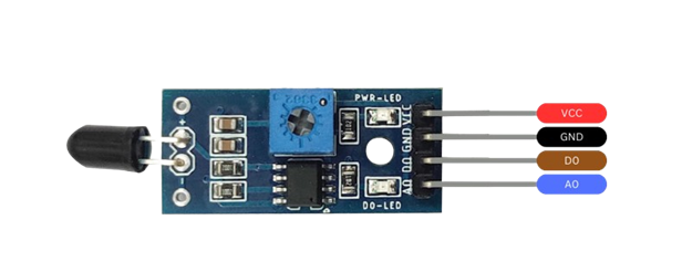
VCC – 3.3V to 5V
GND – GND
DO – Digital Output
AO – Analog Output
Hardware Requirements
1x Arduino
1 x Buzzer
1x Flame Sensor
1x breadboard
Some jumper wire
A Small Lighter or Candle (for testing, under adult supervision)
Circuit Diagram
Connection for Digital Pin (DO):
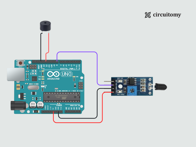
Fig: Interfacing Flame Sensor(Digital) with Arduino
Flame Sensor Configuration
| Flame Sensor Pin | Arduino Pin |
| VCC | 5V |
| GND | GND |
| DO | D7(Digital Pin 7) |
Buzzer Configuration
| Buzzer pin | Arduino Pin |
| Positive Leg Pin | D12(Digital Pin 12) |
| Negative Leg Pin | GND |
Code for Flame Sensor Digital Pin
const int flamePin = 7; // Flame sensor digital pin
const int BuzzerPin = 12; // Buzzer
void setup() {
Serial.begin(9600); // Initialize Serial Monitor
pinMode(flamePin, INPUT); // Set flamePin as an input
pinMode(BuzzerPin, OUTPUT); // Set Buzzer as an output
}
void loop() {
int flameStatus = digitalRead(flamePin); // Read the sensor output
if (flameStatus == LOW) { // Flame detected
digitalWrite(BuzzerPin,HIGH);
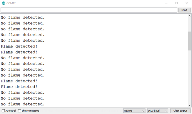
Serial.println("Flame detected!");
} else {
digitalWrite(BuzzerPin,LOW);
Serial.println("No flame detected.");
}
delay(500); // Wait for half a second before checking again
}
How it works:
1. Setup:
I) The flame sensor is connected to pin 7 (input), and a buzzer is connected to pin 12 (output).
II) Serial communication is initialized at 9600 baud to send messages to the Serial Monitor.
2. Loop:
I) Reads the flame sensor status using digitalRead(flamePin).
II) If a flame is detected (LOW signal):
a) The buzzer is turned ON.
b) Flame detected!” is printed to the Serial Monitor.
III) If no flame is detected (HIGH signal):
a) The buzzer is turned OFF.
b) “No flame detected.” is printed to the Serial Monitor.
IV) The status updates every 500 ms.
Terminal:
Circuit Diagram
Connection for Analog Pin (AO):
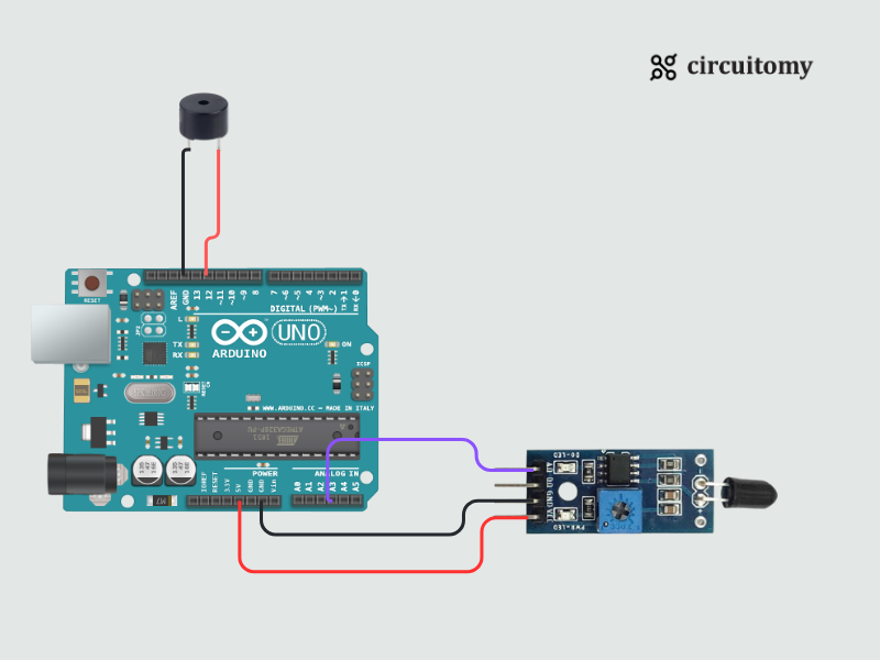
Fig: Interfacing Flame Sensor(Analog) with Arduino
Flame Sensor Configuration
| Flame Sensor Pin | Arduino Pin |
| VCC | 5V |
| GND | GND |
| AO | A3 (Analog Pin 3) |
Buzzer Configuration
| Buzzer pin | Arduino Pin |
| Positive Leg Pin | D12 (Digital Pin 12) |
| Negative Leg Pin | GND |
Code for Flame Sensor Analog Pin
const int flamePinAnalog = A3; // Flame sensor analog pin
const int BuzzerPin = 12; // Flame sensor analog pin
void setup() {
Serial.begin(9600); // Initialize Serial Monitor
pinMode(BuzzerPin,OUTPUT);
}
void loop() {
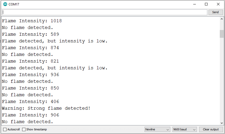
int flameIntensity = analogRead(flamePinAnalog); // Read analog value
Serial.print("Flame Intensity: ");
Serial.println(flameIntensity);
// Check flame intensity levels and display a message
if (flameIntensity < 500) {
Serial.println("Warning: Strong flame detected!");
digitalWrite(BuzzerPin,HIGH);
}
else if (flameIntensity < 850) {
Serial.println("Flame detected, but intensity is low.");
digitalWrite(BuzzerPin,HIGH);
}
else {
Serial.println("No flame detected.");
digitalWrite(BuzzerPin,LOW);
}
delay(500); // Wait for half a second before checking again
}
How it works:
1. Setup:
I) The flame sensor’s analog output is connected to A3, and the buzzer to pin 12.
II) Serial communication is initialized at 9600 baud.
2. Loop:
I) The flame intensity is read using analogRead(flamePinAnalog) and printed to the Serial Monitor.
II) Based on the intensity value:
a) Below 500: A strong flame is detected. The buzzer is ON, and a warning is displayed.
b) Between 500 and 850: A flame is detected with low intensity. The buzzer is ON, and a notification is displayed.
c) Above 850: No flame is detected. The buzzer is OFF.
III) The status updates every 500 ms
Terminal:
Flame Sensor: Digital vs. Analog Pin Comparison
| Feature | Digital Output (DO) | Analog Output (AO) |
| Output | HIGH (No Flame) / LOW (Flame Detected) | Value between 0–1023 (Flame Intensity) |
| Use Case | Simple flame detection (Yes/No) | Measure flame strength or proximity |
| Arduino Pin | Any Digital Pin (e.g., Pin 7) | Any Analog Pin (e.g., A0) |
| Complexity | Easy | Slightly more advanced |