Are you curious about how to measure distances using an Arduino? The HC-SR04 ultrasonic sensor is your gateway to exciting projects like obstacle avoidance robots, parking assist systems, and more. In this tutorial, we will learn how to interface the HC-SR04 sensor with an Arduino board in a simple and fun way.
What is the HC-SR04 Ultrasonic Sensor?
The HC-SR04 is an affordable and widely used ultrasonic sensor that measures the distance between itself and an object. It works by sending ultrasonic sound waves and measuring the time it takes for the sound to bounce back after hitting an object.
How Does the HC-SR04 Work?
1. Trigger: The sensor sends out an ultrasonic pulse (sound wave) when it receives a signal at its trigger pin.
2. Echo: The sound wave travels through the air, hits an object, and returns to the sensor.
3. Distance Calculation: The sensor measures the time it took for the sound wave to return and calculates the distance using the formula:
Distance = (Time × Speed of Sound) / 2
Note: The speed of sound is approximately 343 meters per second in air.
HC-SR04 Specifications
♦ Operating Voltage: 5V
♦ Operating Current: 15mA
♦ Range: 2 cm to 400 cm
♦ Accuracy: ±3 mm
♦ Ultrasonic Frequency: 40 kHz
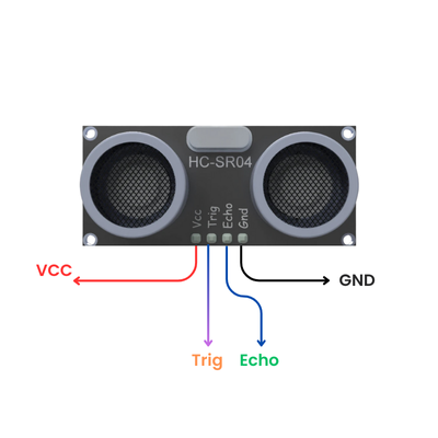
HC-SR04 Pinout
♦ VCC: Connects to 5V on the Arduino.
♦ GND: Connects to the ground.
♦ TRIG: Sends an ultrasonic pulse when triggered.
♦ ECHO: Outputs a signal proportional to the time taken by the pulse to return.
Hardware Requirements
1x Arduino Uno (or any compatible board)
1x HC-SR04 Ultrasonic Sensor
1x Breadboard
Some Jumper wires
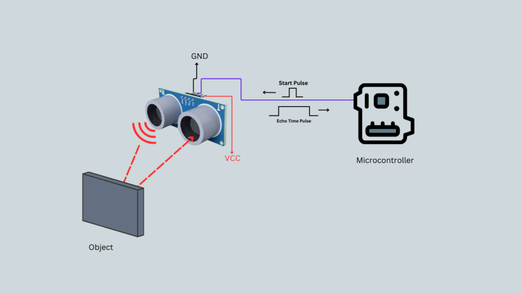
Circuit Diagram
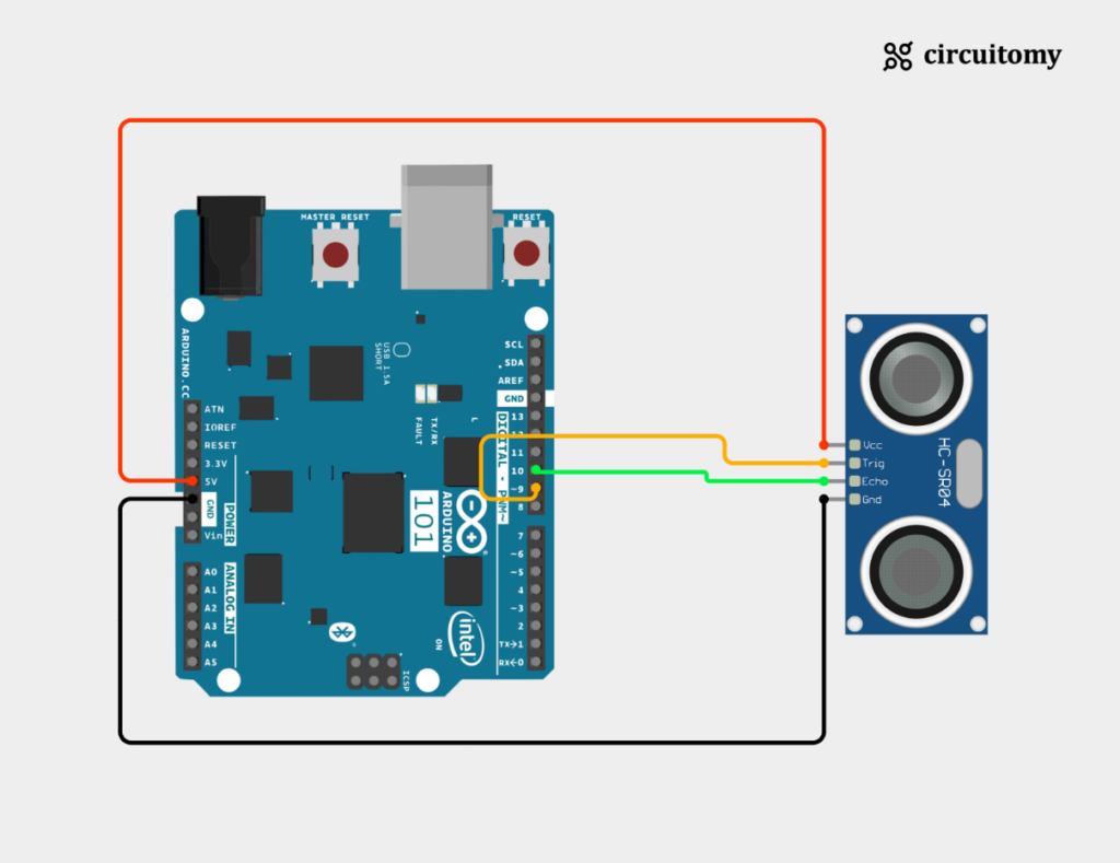
HC-SR04 Configuration
| HC-SR04 | Arduino |
| VCC | 5V |
| GND | GND |
| TRIG | D9 (Digital Pin 9) |
| ECHO | D10 (Digital Pin 10) |
Code
const int trigPin = 9;  // Trigger pin
const int echoPin = 10; // Echo pin

void setup() {
  Serial.begin(9600);       // Initialize Serial Monitor
  pinMode(trigPin, OUTPUT); // Set Trigger pin as OUTPUT
  pinMode(echoPin, INPUT);  // Set Echo pin as INPUT
}

void loop() {
  // Send a 10-microsecond pulse to the Trigger pin
  digitalWrite(trigPin, LOW);
  delayMicroseconds(2);
  digitalWrite(trigPin, HIGH);
  delayMicroseconds(10);
  digitalWrite(trigPin, LOW);

  // Measure the duration of the echo pulse
  long duration = pulseIn(echoPin, HIGH);

  // Calculate the distance in centimeters
  float distance = (duration * 0.034) / 2;

  // Display the distance on the Serial Monitor
  Serial.print("Distance: ");
  Serial.print(distance);
  Serial.println(" cm");

  delay(500); // Wait for half a second
}
1. Variable Definitions
const int trigPin = 9;  // Trigger pin
const int echoPin = 10; // Echo pin
I) trigPin is assigned to pin 9 on the Arduino and is used to send ultrasonic pulses.
II) echoPin is assigned to pin 10 and is used to receive the reflected pulse (echo).
III) Both are declared as constants using const because their values won’t change during program execution.
2. setup() Function
void setup() {
  Serial.begin(9600);       // Initialize Serial Monitor
  pinMode(trigPin, OUTPUT); // Set Trigger pin as OUTPUT
  pinMode(echoPin, INPUT);  // Set Echo pin as INPUT
}
I) Serial.begin(9600): Initializes communication between the Arduino and your computer at a baud rate of 9600 bits per second. This allows data to be displayed in the Serial Monitor.
II) pinMode(trigPin, OUTPUT): Configures trigPin as an output pin so the Arduino can send pulses.
III) pinMode(echoPin, INPUT): Configures echoPin as an input pin to receive the reflected pulse signal.
3. loop() Function
The loop() function runs repeatedly and performs the distance measurement process.
Step 1: Triggering the Sensor
digitalWrite(trigPin, LOW);
delayMicroseconds(2);
digitalWrite(trigPin, HIGH);
delayMicroseconds(10);
digitalWrite(trigPin, LOW);
I) digitalWrite(trigPin, LOW): Ensures the trigPin is initially LOW.
II) delayMicroseconds(2): Adds a short delay (2 microseconds) to stabilize the signal.
III) digitalWrite(trigPin, HIGH): Sends a HIGH signal (5V) to the trigPin to generate the ultrasonic pulse.
IV) delayMicroseconds(10): Keeps the signal HIGH for 10 microseconds, the duration required for the HC-SR04 to emit an ultrasonic pulse.
V) digitalWrite(trigPin, LOW): Turns off the pulse signal.
Step 2: Measuring Echo Duration
long duration = pulseIn(echoPin, HIGH);
I) pulseIn(echoPin, HIGH): Measures the time (in microseconds) that the echoPin remains HIGH. This corresponds to the time it takes for the ultrasonic pulse to travel to the object and back.
Step 3: Calculating Distance
float distance = (duration * 0.034) / 2;I) Formula: The distance is calculated using:
Distance = (Duration×Speed of Sound) / 2
II) Speed of Sound: 343 meters/second or 0.034 cm/microsecond.
III) The result is divided by 2 because the duration includes the time for the sound to travel to the object and back.
Step 4: Displaying the Distance
Serial.print("Distance: ");
Serial.print(distance);
Serial.println(" cm");
I) Serial.print(): Displays text and variable values on the Serial Monitor.
II)The calculated distance is shown in centimeters, followed by the unit cm.
Step 5: Adding a Delay
delay(500);
Adds a half-second delay before the next measurement to ensure the output updates at a readable pace.
How It Works Together
♦ A 10-microsecond pulse is sent to the trigPin.
♦ The echoPin listens for the reflected pulse and measures the time it takes for the echo to return.
♦ The distance is calculated based on the pulse duration and speed of sound.
♦ The result is displayed on the Serial Monitor every 500 milliseconds.
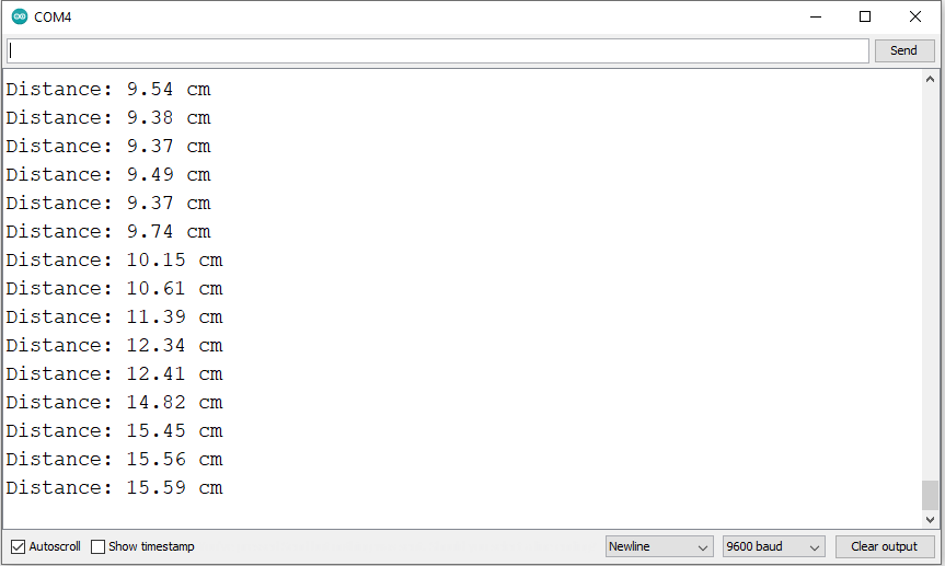
Serial Terminal: