Have you ever wondered how automatic doors know when to open? Or how lights in some places turn on when you walk by? These cool things happen thanks to motion detectors! In this project, you’ll learn how to create your own motion detector using an Arduino and a PIR sensor. Don’t worry if you’re new to this—it’s easier than it sounds, and you’ll be making things work like magic in no time!
PIR Sensor
A Passive Infrared (PIR) sensor is an electronic sensor that detects infrared (IR) light radiating from objects in its field of view. PIR sensors are primarily used for motion detection applications such as in alarm systems, automatic lighting, and security cameras.
PIR Working Principle
PIR sensors work by detecting changes in infrared radiation. Every object that emits heat also emits infrared radiation. The PIR sensor consists of two elements that are sensitive to IR radiation. When no motion is present, the sensor sees equal IR radiation on both elements.
When a warm body, like a person or an animal, passes by, the sensor detects a difference between the two areas, and the sensor triggers.
PIR Sensor Pinout and Specifications:

1.Output: The digital pulse is high (3V) when triggered (motion detected) and low (no motion detected) when idle.
2. Sensitivity range: up to 20 feet (6 meters) 110° x 70° detection range
3. Power supply: 5V-12V input voltage for most modules (they have a 3.3V regulator), but 5V is ideal in case the regulator has different specs.
Hardware Requirements
1x Arduino UNO
1x PIR Sensor Module
1x LED
1x 220R Resistor
1x breadboard
Some jumper wire
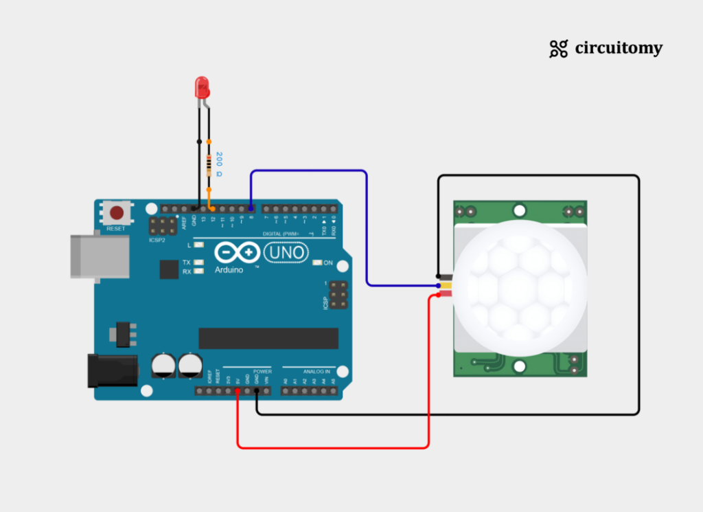
Circuit Diagram

Fig: Interfacing PIR Sensor with Arduino
LED Configuration
| LED Pin | Arduino Pin |
| LED’s Positive (Anode) Pin | D9 (Digital Pin 9) |
| LED’s Negative (Cathode) Pin | GND |
PIR Sensor Configuration
| PIR Sensor Pin | Arduino Pin |
| VCC | 5V |
| GND | GND |
| OUT | D8 (Digital Pin 8) |
Code
#define pirPin 8       // The PIR sensor is connected to pin 8
#define ledPin 9       // The LED is connected to pin 9

long unsigned int lowInTime;  // Stores the time when the sensor output goes LOW (no motion)
long unsigned int pause = 5000;  // Minimum time to wait after detecting no motion (5 seconds)
boolean lockLow = true;   // Used to lock the state when the sensor goes low (no motion)
boolean takeLowTime;      // Flag to check if the low time has been taken
int PIRValue = 0;         // Stores the PIR sensor's state (0 = no motion, 1 = motion detected)

void setup() {
   Serial.begin(9600);
   pinMode(pirPin, INPUT);
   pinMode(ledPin, OUTPUT);
}

void loop() {
   PIRSensor();
}

void PIRSensor() {
   if(digitalRead(pirPin) == HIGH) {
      if(lockLow) {
         PIRValue = 1;
         lockLow = false;
         Serial.println("Motion detected.");
         digitalWrite(ledPin,HIGH);
         delay(50);
      }

      takeLowTime = true;
   }
   if(digitalRead(pirPin) == LOW) {
      if(takeLowTime){
         lowInTime = millis();
         takeLowTime = false;
      }
      if(!lockLow && millis() - lowInTime > pause) {
         PIRValue = 0;
         lockLow = true;
         Serial.println("Motion ended.");
         digitalWrite(ledPin,LOW);
         delay(50);
      }

   }
}
1. Set the PIN Number
#define pirPin 8
#define ledPin 12
pirPin 8 : This sets pin 8 as the input pin where the PIR sensor is connected.
ledPin 12 : This sets pin 12 as the output pin where an LED is connected.
long unsigned int lowInTime;
long unsigned int pause = 5000;
lowInTime : Stores the time (in milliseconds) when the PIR sensor first detects no motion (LOW state).
Pause : Defines the time delay (5 seconds) before turning off the LED after no motion is detected.
boolean lockLow = true;
boolean takeLowTime;
int PIRValue = 0lockLow: A state lock to prevent repeated motion detection messages when the PIR sensor is continuously high (HIGH).
takeLowTime: A flag to track when the PIR sensor first goes LOW, to ensure the time is only recorded once.
PIRValue: Holds the state of the PIR sensor, where 0 indicates no motion, and 1 indicates motion is detected.
2. Setup Function
void setup() {
   Serial.begin(9600);
   pinMode(pirPin, INPUT);
   pinMode(ledPin, OUTPUT);

}
Initializes the serial communication (Serial.begin(9600)) to send messages to the serial monitor.
Sets pirPin (pin 8) as an input for the PIR sensor.
Sets ledPin (pin 12) as an output for the LED.
3. Loop Function
void loop() {
   PIRSensor();
}
Continuously calls the PIRSensor() function to check the PIR sensor state and control the LED accordingly.
4. PIRSensor() Function:
1. Motion Detected (PIR sensor is HIGH):
if(digitalRead(pirPin) == HIGH) {
      if(lockLow) {
         PIRValue = 1;
         lockLow = false;
         Serial.println("Motion detected.");
         digitalWrite(ledPin,HIGH);
         delay(50);
      }

      takeLowTime = true;
   }
If the PIR sensor detects motion (digitalRead(pirPin) == HIGH ), it checks if lockLow is true (which ensures that this block runs only once per motion detection):
Sets PIRValue = 1: This indicates that motion is detected.
Sets lockLow = false: Prevents repeated triggering of the “Motion detected” message while the sensor remains HIGH.
Sends “Motion detected.” to the serial monitor.
Turns the LED on by setting ledPin to HIGH.
Sets takeLowTime = true: Prepares to record the time when the PIR sensor goes LOW (i.e., when no motion is detected).
2. No Motion Detected (PIR sensor is LOW):
    if(digitalRead(pirPin) == LOW) {

      if(takeLowTime){
           lowInTime = millis();
           takeLowTime = false;
       }


     if(!lockLow && millis() - lowInTime > pause) {
         PIRValue = 0;
         lockLow = true;
         Serial.println("Motion ended.");
         digitalWrite(ledPin,LOW);
         delay(50);
      }

   }
If the PIR sensor detects no motion (digitalRead(pirPin) == LOW):
First, it records the time (lowInTime = millis()) when the sensor first goes LOW (if takeLowTime is true), ensuring it only records this once. takeLowTime is then set to false.
Second, it checks if the lockLow is false (i.e., motion was previously detected) and if more than 5 seconds (pause = 5000) have passed since the sensor went LOW:
I) Sets PIRValue = 0: This indicates that no motion is detected.
II) Sets lockLow = true: Resets the state lock, so that when motion is detected again (HIGH), it can trigger the “Motion detected” block.
III) Sends “Motion ended.” to the serial monitor.
IV) Turns off the LED after the 5-second pause by setting ledPin to LOW.
How It Works Together:
1.When motion is detected (PIR sensor is HIGH):
The system detects motion, sends “Motion detected” to the serial monitor, turns on the LED, and sets a lock (lockLow = false) to avoid repeating this action while motion is continuous.
2.When motion stops (PIR sensor goes LOW):
The system waits 5 seconds (defined by pause), then turns off the LED and sends “Motion ended” to the serial monitor. This prevents the LED from flickering on and off too quickly when motion is intermittent.
Code Summary:
1. lockLow and takeLowTime are used to ensure that motion is detected and the corresponding messages/LED changes only happen once per motion event.
2. The 5-second pause ensures a smooth transition when motion stops, avoiding immediate LED off after the sensor goes LOW.
3. PIRValue is used to store the motion state, though it doesn’t play an essential role in this code’s flow other than representing motion detection for potential future uses.
Serial Terminal:

