Are you interested in learning how to create a simple 4-bit binary counter using the ATmega8 microcontroller? This project is perfect for beginners who want to dive into embedded systems and microcontroller programming. In this tutorial, I’ll guide you step-by-step to build a 4-bit binary counter that counts from 0000 to 1111 (0 to 15 in decimal) and displays the output on 4 LEDs.
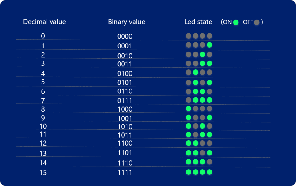
A 4-bit binary counter is a fundamental digital circuit with a wide range of applications in electronics, embedded systems, and computer science. A 4-bit binary counter is an excellent tool for learning the basics of digital electronics and microcontroller programming. It helps you understand:
• Binary number systems (counting from 0000 to 1111).
• How counters work in digital circuits.
• Microcontroller I/O operations (e.g., controlling LEDs).
Components Required
• ATmega8 Microcontroller
• 4 LEDs
• 4 Resistors (220Ω)
• Push Button
• Resistor (10kΩ)
• Breadboard
• Jumper Wires
• Power Supply (5V)
• AVR programmer (USBasp or similar) for uploading code to the Atmega8
Hardware Setup
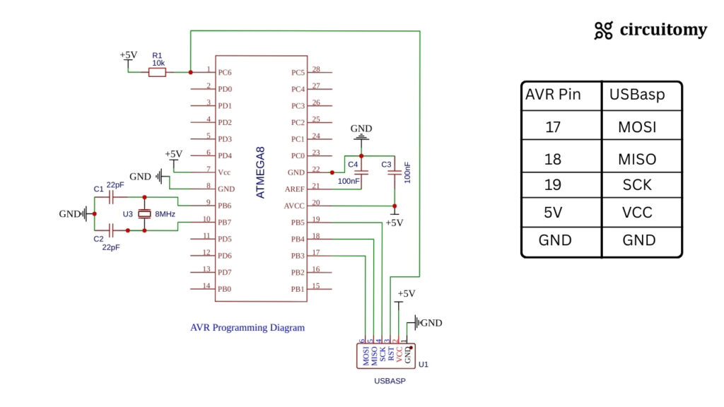
Programming Diagram
Circuit Diagram
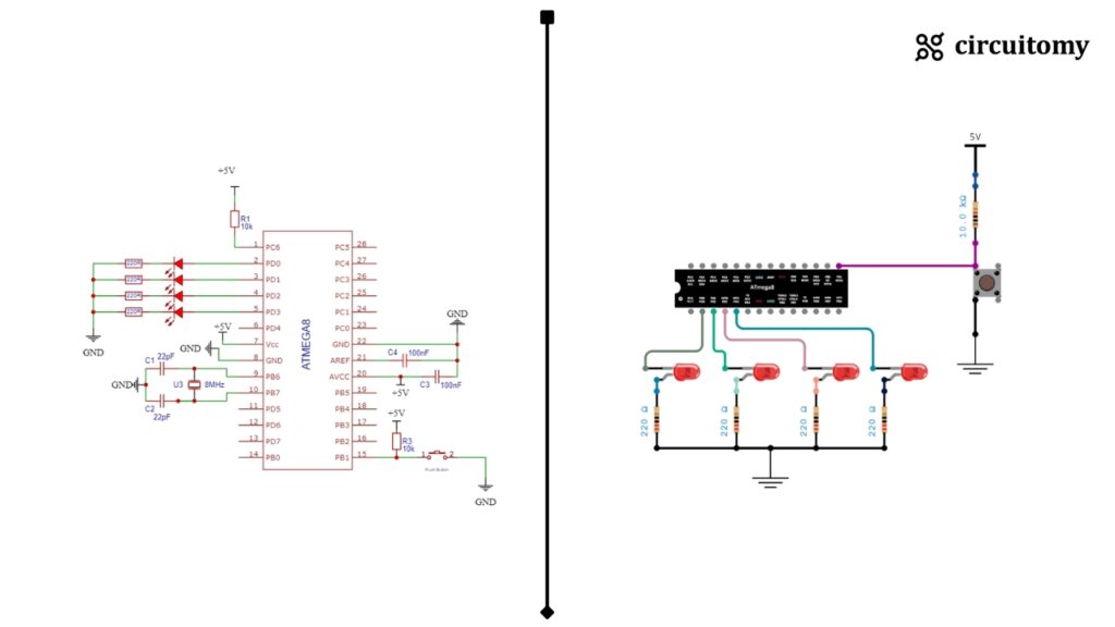
| ATmega8 Pin | Connection |
| PD0 (Pin 2) | LED1 Anode |
| PD1 (Pin 3) | LED2 Anode |
| PD2 (Pin 4) | LED3 Anode |
| PD3 (Pin 5) | LED4 Anode |
| PB1(Pin 15) | Button with pull-up Configuration |
| GND | All LED Cathode (through 220Ω resistor) |
Code
#define F_CPU 8000000UL
#include <avr/io.h>
#include <util/delay.h>

int main(void) {

	DDRD = 0x0F; // Set PD0 to PD3 as output
	DDRB &=~(1<<PB1); // Set PB1 as input
	uint8_t count = 0;

	while (1) {

		if (!(PINB & (1 << PB1))) { // Button Pressed
			_delay_ms(200); // Debounce delay

			count++;

			if (count > 15) {
				count = 0; // Reset counter
			}

			PORTD = (PORTD & 0xF0) | (count & 0x0F); // Output binary to LEDs
			while (!(PINB & (1 << PB1))); // Wait for button release

		}

	}

}Pin Configuration
DDRD = 0x0F; // Set PD0 to PD3 as output
DDRB &=~(1<<PB1); // Set PB1 as input• DDRD = 0x0F → Sets PD0 to PD3 (lower 4 bits of PORTD) as output for LED connection.
Binary: 0b00001111
Meaning:
| Pin | Mode |
| PD0 | Output |
| PD1 | Output |
| PD2 | Output |
| PD3 | Output |
| PD4-PD7 | Input (Unused) |
• DDRB &= ~(1<<PB1) → Sets PB1 as input for the push button.
Counter Variable
uint8_t count = 0;• This variable will store the binary count (0-15).
Button Press Detection
if (!(PINB & (1 << PB1))) {This checks if the PB1 button is pressed.
👉 PINB & (1 << PB1) reads the PB1 pin state.
👉 !() inverts the result, so:
• 0 means the button is pressed.
• 1 means the button is released.
Debounce Delay
_delay_ms(200);It waits 200 ms to avoid multiple signals from the button due to mechanical noise (button bouncing).
Counter Increment & Reset
count++;
if (count > 15) {
	count = 0;
}The counter increases by 1 every button press.
If the counter exceeds 15 (0b1111), it resets to 0.
Binary Output to LEDs
PORTD = (PORTD & 0xF0) | (count & 0x0F);This line sends the lower 4 bits of count to PD0-PD3.
1. (PORTD & 0xF0)
• 0xF0 in binary → 11110000
• This masks the lower 4 bits (D0-D3) and keeps the upper 4 bits unchanged.
• Suppose PORTD = 10101101
Then:
PORTD = 10101101
0xF0 = 11110000
———————————————-
Result = 10100000 (D0–D3 become 0, D4–D7 remain same)
2. (count & 0x0F)
• 0x0F in binary → 00001111
• This takes only the lower 4 bits of count and ignores the upper bits.
3. Combine with | (OR Operator)
• The upper 4 bits stay the same from (PORTD & 0xF0).
• The lower 4 bits get updated with (count & 0x0F).
Example: If:
PORTD = 10101101
count = 00000111
Result:
(PORTD & 0xF0) = 10100000
(count & 0x0F) = 00000111
———————————————————-
PORTD = 10100111
Button Release Wait
while (!(PINB & (1 << PB1)));This line holds the program until the button is released.
Without this line, the counter would increase continuously while the button is held down.