Ever run out of pins on your MCU? Or maybe you just want to feel like a “hardware hacker” by making one wire do the work of two? Today, we are going to learn how to control two different LEDs using just one single GPIO pin.
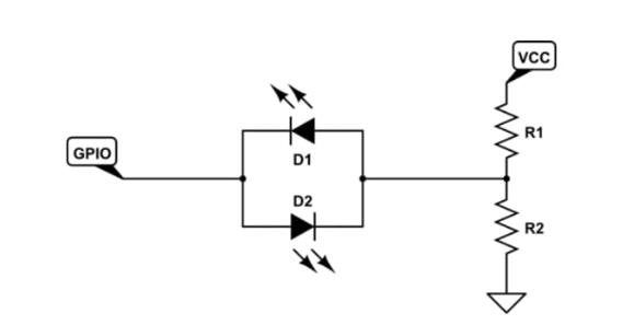
R1 = 470R and R2 = 470R
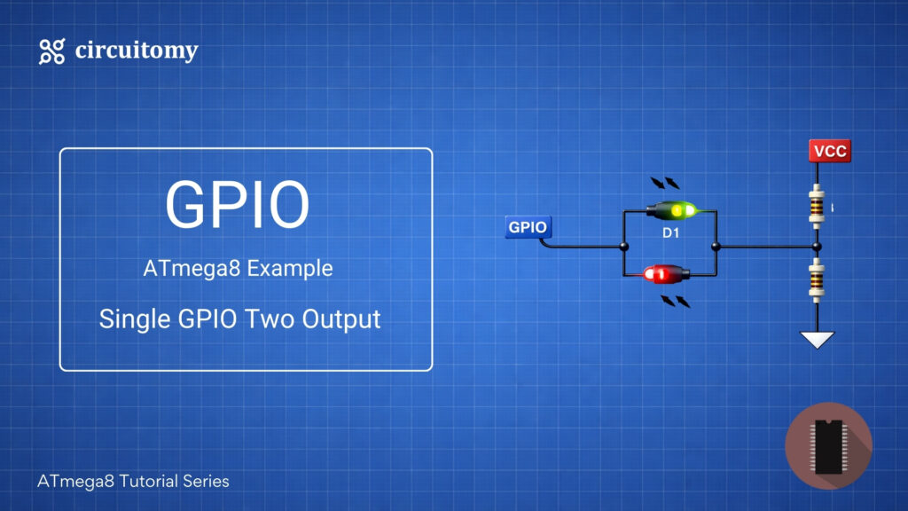
• GPIO = A microcontroller (or chip) output pin.
• D1 & D2 = Two LEDs (could be separate or one bi-color LED with opposite polarity).
• R1 & R2 = Current-limiting resistors.
• VCC = Power supply.
This circuit is a status indicator using two LEDs controlled by a single GPIO pin.
How It Works
When GPIO is HIGH (logic 1):
• The GPIO outputs a high voltage (~VCC).
• Current flows from GPIO → through D2 → R2 → GND.
• Bottom LED (D2) lights up.
• D1 is reverse-biased, so it stays OFF.
When GPIO is LOW (logic 0):
• GPIO outputs ~0V.
• Current flows from VCC → R1 → D1 → GPIO (GND level).
• Top LED (D1) lights up.
• D2 is reverse-biased, so it stays OFF.
When GPIO is FLOATING (input mode, not driven):
• GPIO pin is high-impedance (no drive).
• No current flows.
• Both LEDs are OFF.
Why This Circuit is Useful
• You can show two different states (High/Low) using just one GPIO pin.
• Saves I/O pins on microcontrollers or status chips (battery chargers, regulators, etc.).
• If you use a bi-color LED (red/green, common 2-pin type), it changes color depending on GPIO state.
Code
#define F_CPU 8000000UL
#include <avr/io.h>
#include <util/delay.h>

//OUTPUT Pin Define
#define LED_PIN PB0
#define LED_BIT (1 << LED_PIN)

void blueLedON(){
	DDRB  |=  LED_BIT;
	PORTB &= ~LED_BIT;
}

void redLedON(){
	DDRB  |=  LED_BIT;
	PORTB |= LED_BIT;
}


void bothLedOff(){
	DDRB &= ~ LED_BIT;
}


int main(void)
{

	DDRB |= LED_BIT; // LED on output

    while (1)
    {
	/*
					blueLedON();
					_delay_ms(500);
					bothLedOff();
					_delay_ms(500);
*/
					 redLedON();
					_delay_ms(500);
					bothLedOff();
					_delay_ms(500);

	}
 }
⚠️ A Note for Beginners
Voltage Choice: This works best with a 5V supply. If you use 3.3V, the 1.65V center point might not be enough to reach the “Forward Voltage” (Vf) of some LEDs (like Blue or White).
Power Consumption: Because R1 and R2 are always connected between VCC and Ground, a tiny bit of battery power is always being used. This is why we use 470R or 1k to keep that “leakage” small.